- 您现在的位置:买卖IC网 > Sheet目录17351 > CS51411EVB (ON Semiconductor)EVAL BOARD FOR CS51411 HI FREQ
�� �
�
CS51411,� CS51412,� CS51413,� CS51414�
�APPLICATIONS� INFORMATION�
�THEORY� OF� OPERATION�
�V� 2� Control�
�The� CS5141X� family� of� buck� regulators� utilizes� a� V2�
�control� technique� and� provides� a� high� level� of� integration� to�
�enable� high� power� density� design� optimization.�
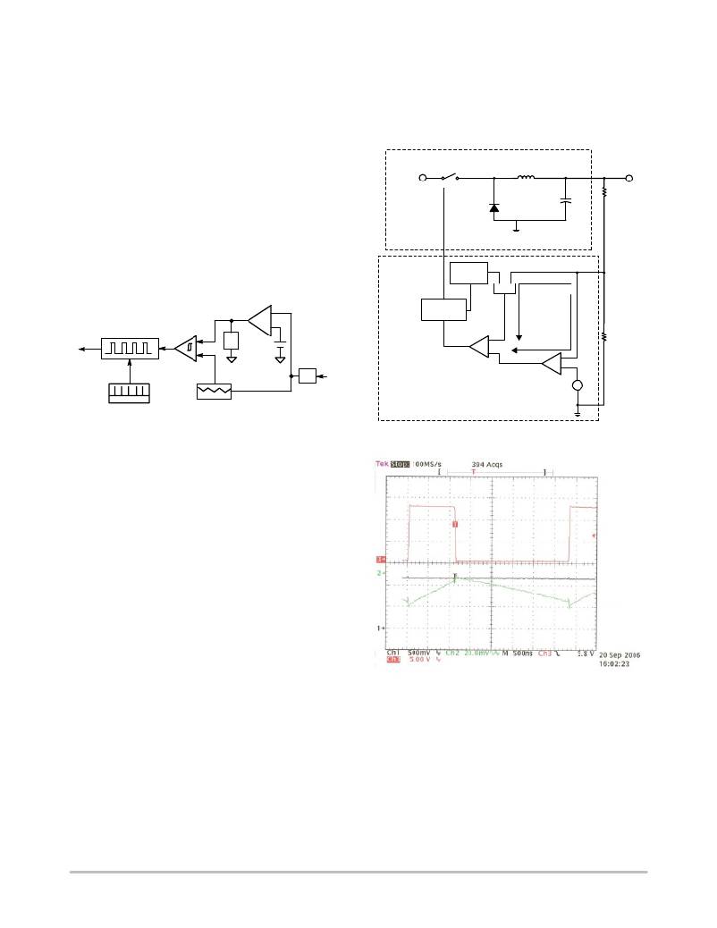
�cycle� modulation� to� occur.� Actual� oscilloscope� waveforms�
�taken� from� the� converter� show� the� switch� node� V� SWITCH� ,�
�the� error� signal� V� C� and� the� feedback� signal� V� FB� (AC�
�component� only)� are� shown� in� Figure� 5.�
�Every� pulse� width� modulated� controller� configures� basic�
�control� elements� such� that� when� connected� to� the� feedback�
�signal� of� a� power� converter,� sufficient� loop� gain� and�
�bandwidth� is� available� to� regulate� the� voltage� set� point�
�against� line� and� load� variations.� The� arrangement� of� these�
�elements� differentiates� a� voltage� mode,� or� a� current� mode�
�controller� from� a� V2� device.�
�Figure� 3� illustrates� the� basic� architecture� of� a� V2�
�controller.�
�V� IN�
�Duty� Cycle�
�Buck�
�Controller�
�S1�
�D1�
�Oscillator�
�Slope�
�Comp�
�L1�
�C1�
�R1�
�V� O�
�Error� Amplifier�
�FFB�
�Latch� S�
�Switch�
�Latch/Drive�
�PWM�
�Z2�
�?�
�+�
�V� REF�
�R�
�V� C�
�SFB�
�R2�
�Clock�
�V2� Control� Ramp�
�V� FB�
�Z1�
�V� O�
�V� 2�
�Control�
�PWM� Com-�
�parator�
�Error�
�Amplifier�
�+�
�?�
�V� REF�
�Figure� 3.� V2� Control�
�In� common� with� V� mode� or� I� mode,� the� feedback� signal�
�is� compared� with� a� reference� voltage� to� develop� an� error�
�signal� which� is� fed� to� one� input� of� the� PWM.� The� second�
�input� to� the� PWM,� however,� is� neither� a� fixed� voltage� ramp�
�nor� the� switch� current,� but� rather� the� feedback� signal� from�
�the� output� of� the� converter.� This� feedback� signal� provides�
�both� DC� information� as� well� as� AC� information� (the� control�
�ramp)� for� the� converter� to� regulate� its� set� point.� The� control�
�architecture� is� known� as� V2� since� both� PWM� inputs� are�
�derived� from� the� converter� ’s� output� voltage.� This� is� a� little�
�misleading� because� the� control� ramp� is� typically� generated�
�from� current� information� present� in� the� converter.�
�The� feedback� signal� from� the� buck� converter� shown� in�
�Figure� 4� is� processed� in� one� of� two� ways� before� being� routed�
�to� the� inputs� of� the� PWM� comparator.� The� Fast� Feedback�
�path� (FFB)� adds� slope� compensation� to� the� feedback� signal�
�before� passing� it� to� one� input� of� the� PWM.� The� Slow�
�Feedback� path� (SFB)� compares� the� original� feedback� signal�
�against� a� DC� reference.� The� error� signal� generated� at� the�
�output� of� the� error� amplifier� VC� is� filtered� by� a� low�
�frequency� pole� before� being� routed� to� the� second� input� of� the�
�PWM.� Each� switch� cycle� is� initiated� (S1� on),� when� the�
�output� latch� is� set� by� the� oscillator.� Each� switch� cycle�
�terminates� (S1� off),� when� the� FFB� signal� (AC� plus� output�
�DC)� exceeds� SFB� (error� DC),� and� the� output� latch� is� reset.�
�In� the� event� of� a� load� transient,� the� FFB� signal� changes�
�faster,� in� relation� to� the� filtered� SFB� signal,� causing� duty�
�Figure� 4.� Buck� Converter� with� V2� Control�
�V� SWITCH�
�V� C�
�V� FB�
�Figure� 5.�
�In� the� event� of� a� load� transient,� the� FFB� signal� changes�
�faster,� in� relation� to� the� filtered� SFB� signal,� causing� duty�
�cycle� modulation� to� occur.� By� this� means� the� converter� ’s�
�transient� response� time� is� independent� of� the� error� amplifier�
�bandwidth.� The� error� amplifier� is� used� here� to� ensure�
�excellent� DC� accuracy.�
�In� order� for� the� controller� to� operate� optimally,� a� stable�
�ramp� is� required� at� the� feedback� pin.�
�http://onsemi.com�
�7�
�发布紧急采购,3分钟左右您将得到回复。
相关PDF资料
RBM06DCWD
CONN EDGECARD 12POS DIP .156 SLD
A9BAG-1604F
FLEX CABLE - AFF16G/AF16/AFE16T
TARQ224K035
CAP TANT 0.22UF 35V 10% AXIAL
A9BAA-0502E
FLEX CABLE - AFJ05A/AE05/AFH05T
AS1329A EB
BOARD EVAL AS1329A
MC34063SMDBGEVB
BOARD EVALUATION MC34063
HCM06DRYN
CONN EDGECARD 12POS DIP .156 SLD
SJA7501-1-1/2-50-BLACK
LOOP BLACK 1 1/2" X 50YD X 0.12"
相关代理商/技术参数
CS51411GD8
功能描述:直流/直流开关调节器 1.5A Low Voltage RoHS:否 制造商:International Rectifier 最大输入电压:21 V 开关频率:1.5 MHz 输出电压:0.5 V to 0.86 V 输出电流:4 A 输出端数量: 最大工作温度: 安装风格:SMD/SMT 封装 / 箱体:PQFN 4 x 5
CS51411GD8G
功能描述:直流/直流开关调节器 1.5A Low Voltage Buck RoHS:否 制造商:International Rectifier 最大输入电压:21 V 开关频率:1.5 MHz 输出电压:0.5 V to 0.86 V 输出电流:4 A 输出端数量: 最大工作温度: 安装风格:SMD/SMT 封装 / 箱体:PQFN 4 x 5
CS51411GDR8
功能描述:直流/直流开关调节器 1.5A Low Voltage RoHS:否 制造商:International Rectifier 最大输入电压:21 V 开关频率:1.5 MHz 输出电压:0.5 V to 0.86 V 输出电流:4 A 输出端数量: 最大工作温度: 安装风格:SMD/SMT 封装 / 箱体:PQFN 4 x 5
CS51411GDR8G
功能描述:直流/直流开关调节器 1.5A Low Voltage Buck RoHS:否 制造商:International Rectifier 最大输入电压:21 V 开关频率:1.5 MHz 输出电压:0.5 V to 0.86 V 输出电流:4 A 输出端数量: 最大工作温度: 安装风格:SMD/SMT 封装 / 箱体:PQFN 4 x 5
CS51411GMNR2G
功能描述:直流/直流开关调节器 BUCK REGULATOR RoHS:否 制造商:International Rectifier 最大输入电压:21 V 开关频率:1.5 MHz 输出电压:0.5 V to 0.86 V 输出电流:4 A 输出端数量: 最大工作温度: 安装风格:SMD/SMT 封装 / 箱体:PQFN 4 x 5
CS51412ED8
功能描述:直流/直流开关调节器 1.5A Low Voltage RoHS:否 制造商:International Rectifier 最大输入电压:21 V 开关频率:1.5 MHz 输出电压:0.5 V to 0.86 V 输出电流:4 A 输出端数量: 最大工作温度: 安装风格:SMD/SMT 封装 / 箱体:PQFN 4 x 5
CS51412ED8G
功能描述:直流/直流开关调节器 1.5A Low Voltage Buck RoHS:否 制造商:International Rectifier 最大输入电压:21 V 开关频率:1.5 MHz 输出电压:0.5 V to 0.86 V 输出电流:4 A 输出端数量: 最大工作温度: 安装风格:SMD/SMT 封装 / 箱体:PQFN 4 x 5
CS51412EDR8
功能描述:直流/直流开关调节器 1.5A Low Voltage RoHS:否 制造商:International Rectifier 最大输入电压:21 V 开关频率:1.5 MHz 输出电压:0.5 V to 0.86 V 输出电流:4 A 输出端数量: 最大工作温度: 安装风格:SMD/SMT 封装 / 箱体:PQFN 4 x 5